Electromagnetic Wave Emission Pattern Measurement System – MRP770
- We provide inexpensive electromagnetic wave emission pattern measurement system which space-saving and installation work not necessary.
- Ideal for developing small wireless devices, information communication devices, and antennas.
The electromagnetic radiation pattern measurement system (MRP770) is a system for measuring the radiation pattern of small wireless devices, information communication devices, antennas, etc. With the rapid progress of IoT, wireless modules are installed in various terminals, and it is becoming more important to understand the antenna performance. This system is a material that introduces an example.
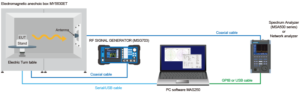
- System Diagram
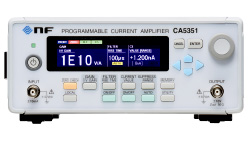
- Measuring Instrument
- Electromagnetic anechoic box
- PC Software
- Calibration example of the EIRP
- Library
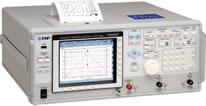
- Spectrum analyzer
Measure the signal that is actively radiated from the EUT.
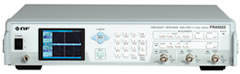
It is mainly used for measuring wireless modules. - Network analyzer
Input a signal to the EUT and measure the signal radiated from the antenna.
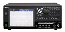
Mainly used to measure passive sources such as antennas. - Signal generator
Input a signal to the EUT and measure the signal radiated from the antenna with a spectrum analyzer.
Mainly used to measure passive sources such as antennas.
*Please contact us for compatible models.
MY5630ET
-

A large anechoic box with excellent versatility, mainly for the sub-GHz to millimeter wave band.
Outside Dimensions
(approx.)2504(W)×1922(H)×1704(D)mm
*excluding projectionsInside Dimensions
(approx.)2010(W)×1140(H)×1210(D)mm Weight
(approx.)765kg Radio wave absorber Pyramidal absorber 8 inch Reflection loss 30dB@1GHz
40dB@3GHz
50dB@5GHz
*typ.Shielding characteristics more than 80dB@1 to 6GHz *typ.
(when using shield sheet more than 60dB)Front door 900(W)×1150(H)mm Maintenance door 675(W)×675(H)mm Turn table φ500mm/30kg in load Uniform static load@center of table
Structure POM(White)Air intake and exhaust tube Included Interface USB, LAN ×each 2pcs
Power supply(AC or DC) , D-sub25, D-sub9, Shield sheet×each 1pc
SMA(J)×5(left side×3, right side×2)
MY5310SU-UP
-

A horizontally long anechoic box mainly for the 2 GHz band to the millimeter wave band (5G).
Three-part structure.Outside Dimensions
(approx.)1963(W)×1323(H)×1140(D)mm
*excluding projectionsInside Dimensions
(approx.)1710(W)×775(H)×775(D)mm Weight
(approx.)500kg Radio wave absorber Pyramidal absorber 4 inch Reflection loss 20dB@1GHz
30dB@3GHz
40dB@5GHz
*typ.Shielding characteristics more than 65dB@1 to 6GHz
*typFront door 516(W)×926(H)mm
*same for both sidesTurn table φ500mm/30kg in load Uniform static load @center of table
Structure MetalAir intake and exhaust tube Not included Interface AC outlet, DC power terminal block(3P), LAN D-sub25×each 1pc
N(J)×2(left/right side ×each 1pc)
MY5310S-UP
-

A space-saving anechoic box mainly for the 2.4 GHz to 5 GHz band.
Two-part structure.Outside Dimensions
(approx.)1345(W)×1323(H)×1140(D)mm
*excluding projectionsInside Dimensions
(approx.)1107(W)×775(H)×775(D)mm Weight
(approx.)350kg Radio wave absorber Pyramidal absorber 4 inch Reflection loss 20dB@1GHz
30dB@3GHz
40dB@5GHz
*typ.Shielding characteristics more than 65dB@1 to 6GHz
*typFront door 516(W)×926(H)mm Turn table φ220mm/10kg in load Uniform static load @center of table
Structure acrylicAir intake and exhaust tube Not included Interface AC outlet, LAN ×each 1pc
USB×2
SMA(J)×8(left/right side ×each4)
PC software for automatically measuring the radiation pattern of horizontal or vertical polarization.
Setting screen
Set the spectrum analyzer, network analyzer, and electric turntable. You can also save and read the set values.
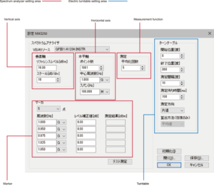
- Vertical axis
Set the reference level and display scale. - Horizontal axis
Set the measurement point, center frequency, and frequency span. - Measurement function
Set the averaging count. - Marker
You can specify a maximum of 5 points for the marker within the set frequency span range. - Turntable
- Specify the measurement start position and end position in steps of 1 degree.
- The rotation step interval is at least 1 degree.
- Set the waiting time in ms unit until the angle to be measured is reached and the spectrum analyzer measurement is started.
- Set the measurement direction to either one-way (CCW) or round-trip (CCW+CW).
Measurement screen
Turn the turntable to the specified angle and perform sweep measurement with the spectrum analyzer. Automatically plot the signal level at the specified frequency on the polar graph.
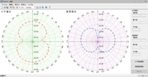
- Horizontal polarization and vertical polarization are measured separately, and the measurement results are displayed on the same GUI.
- Displays the measured, maximum, and average values for both horizontal and vertical polarization.
- Measurement data can be output as a CSV file.
- The unit of measurement of the polar coordinate graph can be switched between absolute value display (dBm) and relative value display (dB). The relative value display is based on the maximum measured value.
*MICRONIX Corporation reserves the right to make changes in design, specification and other information without prior notice.
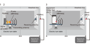
- Antennas with known gains measure in the boresight direction.
Pt[dBm] Effective radiated power (ERP) Gt[dB] Antenna gain Pt eirp[dBmeirp] Equivalent isotropically radiated
power Pt [dBm] + Gt [dB]Pr[dBm] Received power of RF connector part of Electromagnetic anechoic box through receiving antenna + coaxial cable - Find the degree of antenna coupling.
K[dB] Pt eirp[dBmeirp]-Pr[dBm] - Can be measured radiation electricity of measured device (EUT) in reception system same as calibration.
P eirp[dBmeirp] Pread[dBm]+K[dB]
System configuration (Example of wireless module measurement from 1GHz to 8.5GHz)
| Product Name | Model | Quantity |
|---|---|---|
| Electromagnetic anechoic box (Built-in Electric turn table) | MY5630ET | 1 |
| Shield sheet (Maintenance door side) | MY5630-03 | 1 |
| Wooden base | MY5630-04 | 1 |
| Double Ridge Horn Antenna Set (1 to 18GHz) | MY5630-01 | 1 |
| Spectrum analyzer | MSA558 | 1 |
| USB Cable | MI400 | 1 |
| Coaxial cable (0.5m, Receiving antenna to Electromagnetic anechoic box) | MC201 | 1 |
| Coaxial cable (4m, Electromagnetic anechoic box to Spectrum analyzer) | MC203 | 1 |
| Conversion adapter | MA306 | 1 |
| PC software | MAS250 | 1 |
| PC for Measurement | 1 | |
| Serial/USB cable | 1 | |
| Calibration Kit | ||
| SI costs (comprehensive testing, coupling measurement, etc.) | ||
| Carry-in costs (transportation, carry-in, installation, etc.) |
Option (Example of anechoic box MY5630ET)
Doubleridge horn antenna set
| Model | MY5630-01 |
|---|---|
| Type | Doubleridge horn |
| Frequency | 1 to 18GHz |
| Connectors | SMA(J) |
| Other | One set of fixing jig(*1) |
| Features |
|
Log periodic antenna set
| Model | MY5630-02 |
|---|---|
| Type | Log periodic dipole array |
| Frequency | 700MHz to 6GHz |
| Connectors | SMA(J) |
| Other | One set of fixing jig(*1) |
| Features |
|
(*1)Include connecting cables and connectors inside shield box.
Shield sheet (Maintenance door side)
| Model | MY5630-03 |
|---|---|
| Features |
|
MY5630-04
| Model | MY5630-04 |
|---|---|
| Features |
|
*Please contact us for details and combination of the system.