ME8661A
Description
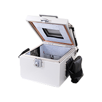
Electromagnetic Anechoic Box/Shielding box Small/Medium Size ME8661A
- Suitable for testing W-CDMA, CDMA, GSM, PDC, PHS, ETC and wireless systems.
- It covers the frequency band of low frequency through 18GHz.
- A receiving antenna of your choice will be mounted.
Specification
This is a simple type shielding box that may be used on a desk.
It is of triple structure, i.e., radio wave absorber, copper plate and aluminum plate.
It covers the frequency band of low frequency through 18GHz.
| Outside Dimensions (approx.) |
820(W)×608(H)×503(D)mm (excluding projections) |
|---|---|
| Inside Dimensions |
700(W)×380(H)×380(D)mm |
| Acrylic resin table | 200×200mm |
| Weight | approx.38㎏ (excluding antenna) |
| Structure | Triple structure composed of radio wave absorber, copper plate and aluminum plate |
| Shielding Characteristics (typ) |
65dB@2.4GHz |
| Reflection loss | more than 20dB@1.2GHz |
| Connectors |
|
| Option |
|
Reference antenna
Reference antenna Spiral antenna
| Frequency range | 2 to 18GHz |
|---|---|
| Antenna gain | -2 to +6dBi(with data) |
| VSWR | Less than 2 |
| Polarization | Right circular |
| Max. input power | 1W @ CW |
| Application | For OBE of ETC |
*Receiving antenna model (Spiral antenna) is same specifications as above.
| Frequency range | 2 to 5GHz |
|---|---|
| Antenna gain | +12.5 to +17dBi(with data) |
| VSWR | 1.4 (typ.), 3.0 (max.) |
| Polarization | Linear |
| Max. input power | 200W @ CW |
| Application | Cellular phone, PHS |
*Receiving antenna model (Horn antenna) is same specifications as above.
| Frequency range | 0.75 to 2GHz |
|---|---|
| Antenna gain | +0.5 to +10dBi(with data) |
| Polarization | Linear |
| Application | Cellular phone, PHS |
*Receiving antenna model (Log periodic antenna) is same specifications as above.
| Frequency range | 300MHz to 6.2GHz (M301-309 According to each specification.) |
|---|---|
| Antenna gain | 2.15dBi(with data) |
| VSWR | Linear |
| Polarization | Cellular phone, Wireless LAN, Bluetooth, etc. |
*Receiving antenna model (Portable antenna) is same specifications as above.
Applications
-
- Application1 : Wireless system test
With a W-CDMA, CDMA, GSM, PDC, PHS, OBE of ETC, wireless LAN, Bluetooth and wireless communication equipment, it is possible to test the wireless system in a free space that is close to actual working conditions (testing of transmission power, transmission frequency, spurious, occupied bandwidth, carrier-off leakage power, adjacent channel power, modulation factor, transmission eye pattern, etc.).
Two optional receiving antenna models, i.e., Model A and Model B, are available. It is, however, also possible to mount an antenna of different specification, if the frequency band and polarization are appropriately specified.
A distance of 30 cm or greater may be provided between the test sample and the receiving antenna. An optional reference antenna is used for calibration of RF coupling degree (loss between front face of test sample and SMA connector of receiving antenna output).
Antenna gain and frequency characteristics data of RF coupling degree are appended to this reference antenna. Although the antenna itself is the same whether a reference antenna or a receiving antenna, a reference antenna is provided with a fixing stand made of acrylic resin, so that it can be placed on the acrylic resin table.
-
- Application2 : Antenna test
Connect a signal source to the reference antenna connector and connect a measuring instrument to the receiving antenna connector. Having done this, antenna characteristics data can be acquired.
-
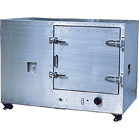
- Application3 : Electromagnetic anechoic box
Capable of using as a mere electromagnetic anechoic box without mounting antenna. It is optimum for simple preliminary experiments for EMC testing and when it is wanted to conduct a test shielded from the external magnetic field.
Library
- Products Catalog
- Technical report
*MICRONIX Corporation reserves the right to make changes in design, specification and other information without prior notice.