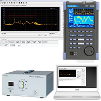
Pre-compliance EMI test system MR2300
- Ideal for “Pre-compliance” preliminary conformance test of EMI official test.
- Total test system including not only antenna, spectrum analyzer for EMI, LISN and PC software for EMI but also anechoic box.
Description
What can be done?
- Two kinds of EMI tests can be carried out.
- Radiated emission test
This test can be performed in the frequency range 30MHz to 1GHz by using an anechoic box and a broadband antenna.
※option : It corresponds to 1GHz or more as an option. - Conducted emission test
This test can be performed in the frequency range 150kHz to 30MHz by using LISN (Line Impedance Stabilization Network).
- Radiated emission test
- The source of noise can be found.
- Magnetic field measurement of PCB in EUT
The source of the emission noise can be found by using a magnetic field probe CP-2SA of option and measuring the magnetic field on the print circuit board.
- Magnetic field measurement of PCB in EUT
Features
-
- EMI Total Test System without Additional Equipment.
As a complete and total test system including not only antenna, spectrum analyzer for EMI, LISN and PC software for EMI but also anechoic box, MR2300 is the first in the world.
In addition, the magnetic field probe (option) is prepared as a problem solution tool.
-
- Compact and broadband antenna by our own development.
The antenna, whose dimensions are as small as 578(W)×401(H)×250(D)mm (MAN101, excluding ground plate) and bandwidth is as broad as 30MHz to 1GHz, was developed by ourselves.
The size of anechoic box also became small by miniaturizing the antenna.
-
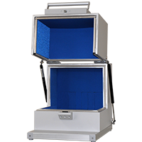
- Small, medium and large anechoic boxes.
 MY5310
For small EUT and equipped with a turntable of 220mm in diameter / 10kg in load.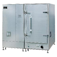 MY5310S/SU
Separate and assembled type that can be carried in a personnel elevator and installed in a narrow space.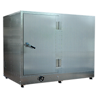 MY5410
For large EUT and equipped with a turntable of 756mm in diameter / 100kg in load..
- Calibration of the entire system
- Small, medium and large anechoic boxes.
The calibration as the whole system like corrections of the antenna gain, attenuation of LISN and conversion into 3 meters in measurement distance is performed in Spectrum analyzer and PC software.
The user only reads the measurement result on the PC screen as it is.
-
- Confirmity to regional and international standards
MR2300 is based on CISPR11(classA/B,group1), CISPR22(classA/B), EN55011(classA/B,group1), EN55022(classA/B), VCCI(classA/B) and FCC part15 subpartB(classA/B).
Overview
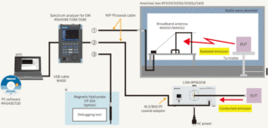
When ①, ② or ③ in the whole system chart shown above is connected to <About magnetic field probe CP-2SA> [RF INPUT] of Spectrum analyzer MSA438E/538E/558E for EMI, the radiated emission test, the conducted emission test or debugging to remove the source of disturbance noise respectively can be performed.
*PC and CP-2SA are not included in the system price.
-
- Radiated emission test
By connecting anechoic box MY5310/S/SU・5410 and MSA438E/538E/558E with an accessory N(P-P) coaxial cable, the radiated emission test is done within 30MHz to 1GHz.
After receiving the disturbance noise that EUT (Equipment under test) radiates in the air with broadband antenna MAN101/102, it is input to MSA438E/538E/558E. The antenna gain of MAN101/102 is corrected and the electric field strength (dBμV/m) is calculated in MSA438E/538E/558E.
The calculation result is displayed with the limit line by the EMI standard on the screen of a personal computer after forwarded there through the USB cable MI400 communication and converted into 3 meters in measurement distance.
-
- Conducted emission test
By inserting an accessory N(J)/BNC(P) coaxial adaptor in the [RF OUT] terminal of LISN(MPW201B) and then connecting to MSA438E/538E/558E with N(P-P) coaxial cable, the conducted emission test is done within 150kHz to 30MHz.
The disturbance noise that EUT discharges into the power supply line is input to MSA438E/538E/558E through LISN. The attenuation of LISN is corrected and the noise is converted into the unit of dBμV in MSA438E/538E/558E.
The data is displayed with the limit line by the EMI standard on the screen of a personal computer after forwarded there through the USB cable MI400 communication.
-
- Search of the source of disturbance noise
The magnetic field distribution on a print circuit board can be precisely measured by using magnetic field probe CP-2SA of option.
As a result, it is very convenient as a debugging tool because the source of disturbance noise that exceeds the limit line can be easily found out.
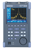 Handheld Spectrum Analyzer MSA438E
This is a model in which EMI measurement function is added to MSA438.
Measurement frequency:50kHz to 3.3GHz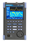 Handheld signal analyzer MSA538E
This is a model in which EMI measurement function is added to MSA538.
Measurement frequency:20kHz to 3.3GHz-
Handheld signal analyzer MSA558E
It is possible to conduct EMI test without troublesome setting.
Measurement frequency:20kHz to 8.5GHz 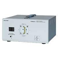 LISN・MPW201B
Line Impedance Stabilization Network
Library
- Products Catalog
- Technical report
*MICRONIX Corporation reserves the right to make changes in design, specification and other information without prior notice.